
TAUSTRUP OVESEN COOPERATION OBSERVATORY
TAUSTRUP OVESEN COOPERATION OBSERVATORY
THE
COOKBOOK CCD CAMERA
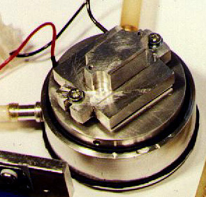
THE CAMERA HOUSEIn October 1997 we finished building our Cookbook CCD camera. The CCD camera has been made according to the documentation in: "The CCD Camera Cookbook" , written by Richard Berry, Veikko Kanto and John Munger.
The camera is based on the Texas Instruments CCD chip TC245.
The main part of the camera house has been made as described in The Cookbook. One of the modifications has to do with the to wires to the Peltier element. Instead of making slots in the lower section of the camera house I mounted a female adapter on the side of it. I was advised not to ground the minus pole to the Peltier element so I had to isolate the female adapter from the metal of the camera house - this was done by mounting the female adapter on a Pertinax plate and gluing this on the camera house.
In order to make the camera house airtight I have used O-rings to fit in at the top and bottom. The bottom O-ring can be seen here.
The preamplifier board housing is another minor change in the design - it's smaller and there is a bottom plate under the board for better shielding from noise.
The optical window is made from a camera UV-filter - thickness: 2.8 mm's.
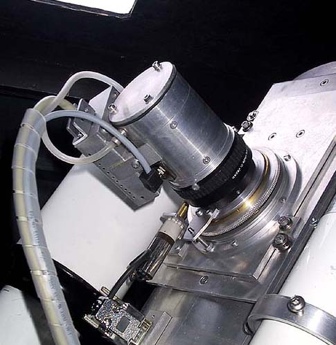
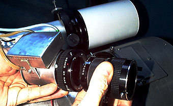
The CCD camera house is equipped with a Nikon female-adapter for quick mount on the telescope. It's also possible to mount any Nikon lens on it and just focus.
The telescopes "fine focus" function can be controlled from "the control room" under the observatory. A geared motor drives the draw tube.
CABLING
We do not use ribbon cable at all. Instead we use shielded cable both for the connection between the preamp and interface and from interface to PC. There has been no problems with noise - noise tests shows RMS values below 1 at 378 x 242 mode.
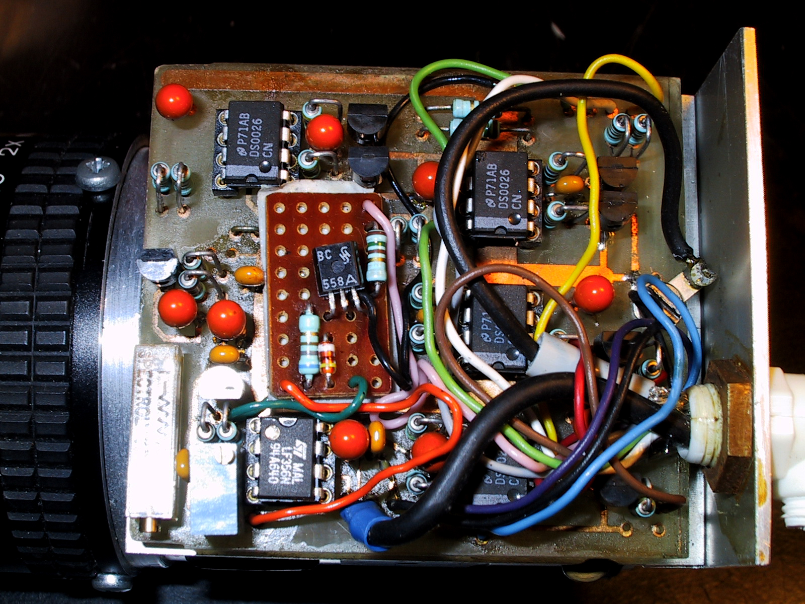
THE PREAMPLIFIER (image)
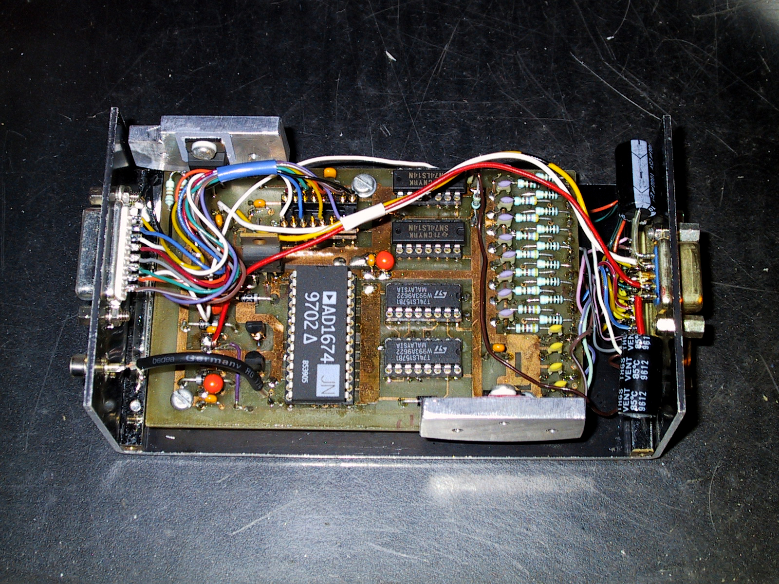
The two two-sided printed curcuit boards are homemade. They are protected by a thin layer of "FLUX" - SK10.THE INTERFACE BOARD (image)
Flemming made the Interface box. It's very solid and almost airtight to prevent unwanted visitors (bugs) from entering without permission. The upper part (not mounted) serves as heat sink for VR1 and VR3.
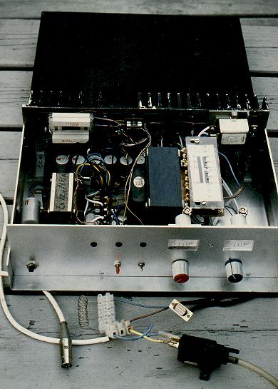
THE POWER SUPPLYThe power supply is a slightly modyfied version to the one described in The Cookbook.
We use two seperate transformers - one for the 18-0-18 volt supply and one for the pump and Peltier element.
We decided to have variable output for both the Peltier and the pump. This has proved to be a good idea as the pump runs well at 3 volts. Normally it runs at 3.5 volts yielding a flow of approximately 300 ml per minute, and this is adequate.
We use a 15 volt peltier element in order to avoid too thick leads. Accordingly the power supply gives out a higher voltage for this unit.
When operating the output transistor for the Peltier element became quite hot, so we decided to mount a 12 volt fan (not shown in this picture) on the outside of the heat sink. The fan is connected parallel to the Peltier output.
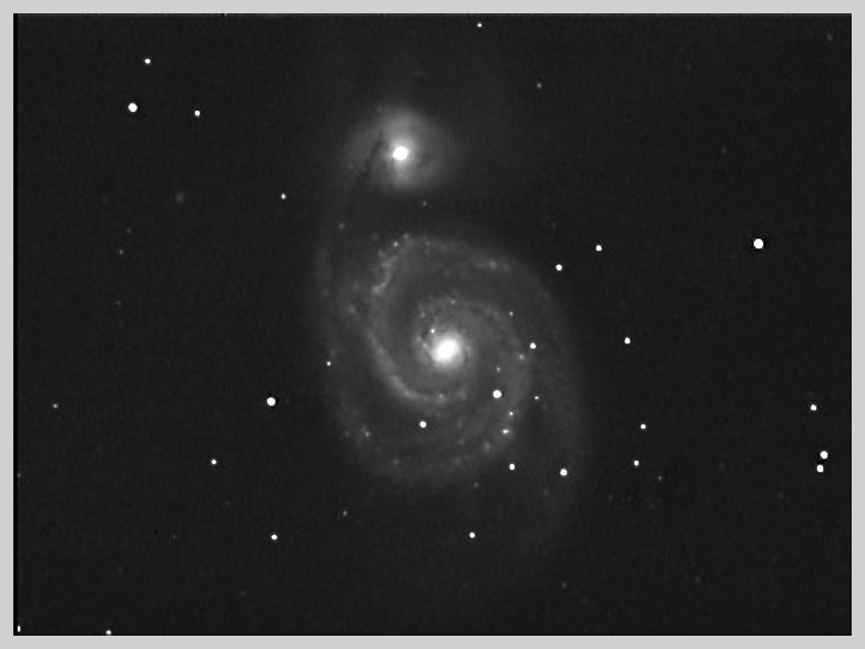
Output voltages can be monitored on the the two meters.THE LDC MODIFICATION
The picture of M-51 has been taken after accomplishing the "LDC" (Low Dark Current) modification. It's a 3 x 3 minutes exposure. The FITS-frames were stacked by Steven Lee, Australia. For this purpose Steven uses "PCVista" and "XVista" - these programs are freely available.
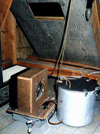
THE COOLING SYSTEM
The cooling system design is different from the system described in The Cookbook. Apart from the 3mm silicon tubing the system consists of a 10 liter aluminium tank, a windshield washer pump, a radiator and a fan . The tank holds approximately 5 litres of cooling liquid. We have found that undiluted windshield washing liquid works fine with the pump as it makes it run more smoothly.
On the way back from the cooling labyrinth to the tank the liquid passes through the radiator. The cooling fan from a PC power supply passes air through the radiator, and this keeps the cooling liquid at ambient temperature.
This however gives you a problem when the air temperature drops during the night - as the temperature of the cold finger and the chip changes with it. A thermometer sensor is placed in the cooling liquid and temperature can be monitored in the "control room". A stable cooling liquid temperature can be accomplished by stopping the fan from time to time allowing the returning liquid to give away heat to the tank.
THE "FITS" PROGRAM
We use Frank Sorensen's "FITS" program. It makes it very easy to handle both dark frame and flat field corrections. Stacking of images is no problem - you don't have to point out guide stars, the program does that for you. It runs on Windows 95 and is still undergoing improvements.
Compare two images of the galaxy NGC891 taken on film and with CCD
EYEPIECE PROJECTION
The Cookbook Camera has proved to be excellent for eyepiece projection. A modifyed teleextender serves as eyepiece holder. Equipped with a 6 mm Kellner eyepiece the system works with a focal length of about 7.5 meters giving a field of view of approximately 3 arcminutes.
In order to get the best result a shutter between the optics and the CCD chip is necessary to prevent light from the object from affecting the image during readout.
Exposure times varies between 0.1 and 0.5 sec. - the latter giving a quite extensive histogram reaching about 2000 counts.
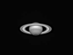
Saturn taken November 2. 1999 - this is a 7 image stack. Seeing conditions were not perfect this night. Exposure time 0.2 sec. Focal length: 9.9 meters. Resolution: 252 x 242.The image has been sharpened by using the 7x7 150 filter - it's one of several sharpening filters available in the "Fits" program developed by Frank Sorensen.
Other planetary images are available.
First page